
Geometry, not appearance
What an SVG to DXF converter actually produces
SVG and DXF describe vector geometry for different jobs. This converter translates supported SVG outlines into CAD entities rather than taking a screenshot.
SVG is a web vector format with paths, basic shapes, colors, filters, text, and CSS. DXF is an exchange format for CAD and manufacturing software. A useful converter extracts geometry, applies the SVG viewBox and transforms, flips the vertical axis for CAD coordinates, and writes physical dimensions.
The output keeps outlines, not the complete visual design. Fill, gradients, stroke color, and stroke width are not manufacturing geometry. A thick stroke becomes its center path unless expanded first. GlyPho reports unsupported content and open paths before export.
Three-step workflow
How to convert SVG to DXF online
Use the workbench in order: inspect the source, define the intended scale, then review the generated drawing before downloading it.
- 01
Choose one SVG
Drop a file or use the picker. The browser checks the SVG root, local references, shapes, dimensions, open paths, and unsupported elements without uploading the file.
- 02
Set units and accuracy
Confirm millimeters or inches, enter the required width or height, and keep the aspect ratio locked unless the design intentionally needs non-uniform scaling.
- 03
Preview and download
Review the DXF geometry preview, warnings, entity count, open-path count, and final dimensions. Download only after the drawing matches the intended CAD scale.
Input matters
Complex illustration versus clean line art
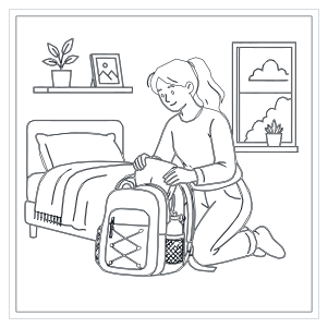
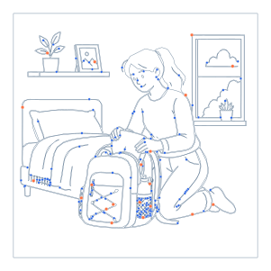
One illustration shown as the styled SVG, its real DXF outline, and a geometry network.

01 / SVG
Duotone source
Blue fills and black outlines style the SVG; DXF retains its reviewed geometry, not these visual treatments.
02 / SVG
DXF outline result
Actual DXF entities expose duplicate edges, open contours, and machining paths.
03 / SVG
Geometry network
Sampled nodes expose path density and fabrication complexity in the same drawing.
Workshop destinations
DXF for laser cutting, CNC, and CAD
A converted file is a starting drawing for the receiving application. Material, machine, and operation settings remain the responsibility of that workflow.
Laser cutting
Turn logos, signage, ornaments, and panel profiles into importable DXF outlines. Check duplicate contours, open paths, and physical size before assigning cut, score, or engrave operations.
CNC routing
Move vector profiles into CAM or CAD before generating toolpaths. Cutter diameter, depth, tabs, feeds, speeds, and machining order still belong in the target software.
CAD drafting
Use an SVG diagram or icon as editable CAD reference geometry. Import into a new drawing, verify the unit scale, then copy approved entities into the production model.
Scale contract
SVG viewBox, millimeters, and inches
A viewBox defines an internal coordinate system; it does not always define a real-world size. The tool separates source coordinates from DXF output dimensions so scale is explicit.
Dimensions using mm, cm, in, pt, pc, or px are normalized at 96 pixels per inch. With only a viewBox, its numbers define proportions and preflight asks you to confirm millimeters or inches.
Standard accuracy defaults to 0.1 mm or 0.004 in. Fine adds points for detailed curves; Draft uses fewer. More points cannot repair a poor source or improve machine accuracy.
- Default output
- Millimeters with the source aspect ratio locked. Change the unit before typing final workshop dimensions.
- Coordinate direction
- SVG's downward Y direction is converted into the upward CAD convention while preserving the visible orientation.
- DXF unit marker
- The exported HEADER includes the appropriate INSUNITS value for millimeters or inches.
Current conversion boundary
Supported SVG elements and intentional limits
The first release focuses on common outline geometry and predictable local references. Preflight blocks content that could silently remove important geometry or access another resource.
Converted geometry
- Path, rectangle, circle, ellipse, line, polyline, and polygon.
- Nested groups with translate, scale, rotate, skew, and matrix transforms.
- Local use references with cycle and depth protection.
- Lines, circles, arcs, and polylines on one compatibility-first DXF layer.
Blocked or not preserved
- Live text is blocked; convert lettering to vector outlines in the source editor first.
- Scripts, DTD, foreignObject, external URLs, and embedded raster images are rejected.
- Clip paths, masks, filters, and CSS-driven visibility trigger review because their visible result may differ.
- Fill, gradient, stroke color, stroke width, and layer colors are not written as DXF appearance.
Preflight notes
Text, strokes, open paths, and complex effects
Most SVG-to-CAD surprises come from artwork that looks complete on screen but does not contain the manufacturing outline a machine expects.
Text is not an outline
Fonts vary between systems. Convert text to paths in the design application, then verify counters and overlapping letters.
A thick stroke is still one path
Stroke width changes appearance, not exported centerline geometry. Expand the stroke first when both edges must become cut boundaries.
Open paths need an operation
Open contours can suit engraving or scoring but fail as closed cuts or pockets. The result reports them instead of closing geometry automatically.
Effects can hide the true outline
Masks, clipping, filters, and CSS can hide underlying paths. Simplify the intended vector geometry before production.
Browser-local by design
Private SVG to DXF conversion
Conversion runs in the current browser session without an account, server upload, or cloud storage.
Local file reading
Your SVG is read locally and remains in this browser tab.
Worker processing
A Web Worker handles geometry and DXF generation away from the interface.
No automatic publishing
Only you decide whether to download the generated file or clear the current drawing.
Restricted inputs
External references and active content are rejected before conversion rather than fetched or executed.
Drawing questions
SVG to DXF converter FAQ
Short answers about file compatibility, dimensions, curve quality, and what to check in downstream CAD software.
Can I convert SVG to DXF for free?
Yes. Convert one SVG at a time for free without sign-up. The 4 MiB file is processed locally in a modern browser.
Will the DXF match my SVG colors?
No. The output is geometry on one compatibility-first layer. SVG fills, gradients, stroke colors, and effects are not preserved.
Why does my CAD app import the wrong size?
Confirm millimeters or inches and the final dimensions before download. Check the receiving application's import unit instead of relying on automatic detection.
Which curve accuracy should I choose?
Start with Standard. Use Fine for detailed curves that need extra points, or Draft when fewer vertices matter more.
Does the converter support text?
Live SVG text is blocked because fonts and text metrics can change geometry. Convert text to outlines first.
What should I inspect after import?
Verify dimensions, orientation, duplicate contours, open endpoints, curve smoothness, and shape count before creating a machine job.
Continue the vector workflow
Related SVG tools
Create, trace, or optimize the source vector before sending reviewed geometry into the DXF workbench.
SVG Compressor
Clean SVG markup and compare the exact file-size change before conversion or web delivery.
Image to SVG Converter
Trace a PNG, JPG, JPEG, or WebP image into editable vector paths before CAD review.
SVG Icon Generator
Create a new SVG icon, then inspect and prepare its outlines for a DXF workflow.